Universal Microsystems
High precision, restrictive flow orifices for
gas flow control


Phone: 408-727-1313
E-mail Us
To Navigate this Page Click on the Subject Below

Contol flow with Pressure
Flow splitting
Backfill a chamber

Limit Catastrophic Gas Flows
with
Precision Flow Orifices
Filter/Limiter Combination
Flow limiters can be used to cap the unregulated flow from a gas stick in case of a catastrophic downstream failure. A failure can be due to a line break or a valve in a stuck open position. Without a flow limiter the resulting catastrophic flow can overwhelm the downstream pumping or gas discharge system.

Consider the arrangement shown in the figure which shows a filter, the limiter R and an MFC with the gas outlet. The flow limiter places an absolute cap on the maximum flow through the system set by the line pressure downstream from the filter designated by Pl .

Universal Microsystems and TEM Filter offer an ultraclean filter with a built-in flow limiter. (See Flow Control Filter ). This combination unit is available in the standard lengths used by current filters making for easy retrofit. In addition, models are available in which flow limiter is detachable from the filter. Consequently, if the process should change it is a simple matter to replace the limiter with one having a different value. Moreover, a clogged filter can be replaced without replacing the limiter.

The filters used in these units are either SS or Ni media and suitable for inert and anhydrous corrosive gases. Both filters result in less than 1 particle/ft3 and THC and moisture content less than 10 ppb.

Design Guide
Choosing a flow limiter is straight-forward. A general recommendation is to choose a restrictor with a catastrophic flow that is some multiple of the rated flow of the MFC. To find the desired model number convert the desired catestrophic flow for the gas species involved into its nitrogen equivalent by dividing by K given in the Step by Step table on the order information page. Then look up the model number from the table. Custom models are available.

Values of P cannot be too low or the MFC will not function correctly. If the limiter is choosen so that the catastrophic flow is 2X-3X the process flow then P will be 6-13 percent of Pl respectively. If a greater pressure drop than 13percent of Pl can be tolerated than a maximum flow of 1.5X can be deployed.

Do not use a 1.5X ratio with the lighter gases if the system must be tested with nitrogen gas. Gases lighter than nitrogen have a higher flow through a given orifice at the same pressure. Therefore, limiters for H2 and He should have respectively 3.7X and 2.7X the maximum rated flow of the MFC so that the same slm flow rate of nitrogen can be achieved during system test.

Return to Menu
Simple, Accurate Flow Control
with
Precision Flow Orifices
If you need accurate flow control but you don’t want the bother of electrical control lines and the expense with mass flow controllers use the system in the figure above. All that is needed is a pressure regulator and a valve (both probably in stock) and a Precision Flow Orifice available from Universal Microsystems (picture above). Connect these three items as shown in the schematic.

Set the pressure regulator so that its outlet pressure is 15 PSIG or greater. Then, if the pressure downstream from the orifice is an atmosphere or less the flow through the orifice will depend only upon the regulator’s outlet pressure. Any variation in the downstream gas conductance will not affect flow through the orifice at all. To get the desired flow, choose a Precision Flow Orifice from the table in the order information page. The valve initiates flow which can be activated with a simple pneumatic or solenoid control. This arrangement produces a single set point flow which is suitable for many applications that do not require flow programmability.

DESIGN GUIDE

The pressure regulator approach to mass flow control is highly accurate when set up properly. The first consideration is the drop in the outlet pressure with flow through the regulator. These values are published by the regulator manufacturer. For example, if there is a 2 PSI drop at the flow conditions desired, just add 2 PSI to the outlet pressure during set up. The second consideration is the supply pressure effect (SPE). Choose a pressure regulator with a relatively low SPE coefficient (~1) which gives the change in the outlet pressure for every 100 PSI change in the line pressure. In that way, line pressure fluctuations of 10 PSI or so will have a negligible effect on the flow through the orifice.

The accuracy of the pressure based flow control is well within +/- 2 percent just with a nominal pressure setting. It can be made nearly exact by matching the pressure regulator output with the calibrations from the flow orifice. Stability is also quite good. With sequential valve opening and closing the pressure output variation is +/- 0.2 percent from readily available regulators. Moreover, the response of this system is fast (~1 sec) and determined primarily by the ability of the regulator to stabilize its output once flow is initiated. In addition, the leakage of this system is lower than with MFCs due to the superior closing of the typical valve compared to the seals in an MFC.
 

Return to Menu
Flow Splitting Applications
with
Precision Flow Orifices

Flow splitting creates multiple downstream lines with only one MFC. In this application the output from one MFC is split into two or more outlets using precision flow orifices. The down-steam flow rate will have precise ratios although typically the flows in the different streams are equal. Flow-rate precision of +/- 2percent is achieved.

DESIGN GUIDE

The proper selection of the Precision Flow Orifices for flow splitting sets up a sonic flow condition through the orifices (i.e. the speed of the gas molecules through the orifice is the speed of sound). Under sonic flow the flow-rate through the orifice is a function of the up-steam pressure only. Therefore, minor differences in the gas conductance in the down-steam piping will have no effect on the flow-rate. The practical condition for sonic flow is that the upstream pressure must be at least twice the down-steam pressure.

The second design consideration is that at the maximum flow the pressure drop through the MFC must be some minimum in order for it to function correctly. This pressure drop should be typically 8-10 PSID from the line pressure. For example, let the line pressure be 30 PSIG, the outlet at vacuum, the total maximum flow be 2 SLM with flow splitting into two equal lines. Then, the proper orifice would be the one that provides 1 SLM flow at 20 PSIG to vacuum.

A wide range of flows is possible. As the MFC lowers the total flow the pressure drops upstream from the orifices. In the example above, when the MFC flowed its maximum 2 SLM, the pressure to the flow splitters was 20 PSIG or 34.7 PSIA. If the MFC lowered the flow rate to 0.2 SLM the pressure would drop by a factor of 1/10 to 3.47 PSIA. This would still be sonic flow for a vacuum outlet.

Return to Menu
Backfill a Chamber
in
a Precise Time
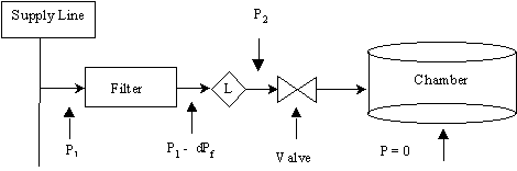
Consider a straightforward backfill system as shown in the figure consisting of a supply line at a pressure Pl with a filter, a valve and a flow limiter, L. L has a rating that its flow is Qs at a pressure equal to (Pl - dPf ), where dPf is the pressure drop across the filter. With the chamber at a vacuum the gas will flow at Qs when the valve opens. Assuming (Pl - dPf) is at least 15 PSIG the flow L will be a constant Qs until the chamber reaches atmospheric pressure. Assuming there is no loss of gas from the chamber during backfill, the time is given simply by:

Time = V / Qs

where V is the volume of the chamber. More generally, the time to fill the chamber to a pressure P2 is given by:

Time = (V / Qs ) x (P2 /14.7)

Where P2 is in PSIA.

DESIGN GUIDE

The equations above are valid for 0 < P2 < (Pl - dPf)/2. Practically, this is always the case for typical values of Pl and dPf. For calculating time to pressurize the chamber to a P2 greater than (Pl - dPf)/2 one has to add a term equal to integrating the flow for sub-sonic conditions. (See Technical Reports).

Values of dPf are published by the filter manufacturer and depend up flow and Pl. For example with the TEM Filter 3775 with a 30 PSIG value for Pl and a flow of 25 slm the pressure drop is 5 PSI. At 25 PSIA a Universal Microsystems’ Model B-900-VS-11 flow limiter flows 25 slm (see table in Order Information section). Consequently, a 5 liter chamber would fill in 12 secs.

Universal Microsystems and TEM filter offer an Ultrapure filter with a built-in flow limiter. (See Flow Control Filter ).

Designers must also be aware that line pressures can vary considerably if there are multiple users on the supply line. In order to assure accurate and repeatable backfill times consider adding a pressure regulator before the filter.

Return to Menu
Universal Microsystems